Thinking inside the hesper
Hello👋 we are Team Kalki. This website is about our submission for NASA International Space App Challenge on challenge named “ Exploring Venus Together”
Start ReadingIntroduction
Regardless of being the twin planet of Earth, the origin, history, and surface composition of Venus is poorly known owing to a lack of space exploration. With a pressure of 90 bar and a temperature of 475 degrees Celsius [1], such an environment is synonymous with hell. Due to the extreme conditions, the landers sent to the venus's surface could stand only a few hours running. Our key challenge in exploring Venus lies in making reliable energy sources that can withstand such severe conditions, as NASA has planned for a Long-Live In-Situ Solar System Explorer(LLISSE) to operate for 60 days with a minimized cell discharge rate. Its requirements are given below.
| Pulse Power | 10W for 2 mins in every 8 hours |
| Pulse Energy | 60Wh |
| Baseload Power | 0.01 W |
| Duration for work | 1440 hr / 60 days |
| Baseload energy | 14.4 Wh |
| Total required energy | 74.4 Wh |
| Working Temperature | 400-500 degree Celsius [2] |

Solid Oxide Fuel Cell (SOFC)
Considering energy requirements for a lander mission, the most
promising solution we discovered is a Low-Temperature
Solid Oxide Fuel Cell. Fuel cells are an ideal candidate as, in comparison to conventional
batteries, they provide
higher power density, are scalable, and provide mass and volume savings for an extended period of
operation of landers.
A fuel cell is an electrochemical device that generates electricity through the continuous flow of
reactants. It is
extremely efficient because, unlike other electrochemical sources that must be converted to thermal,
mechanical, and
then electrical energy, it converts directly to electrical energy in a one-step process. It is a
conversion device that
works until fuel gases and oxidants are supplied to electrodes.
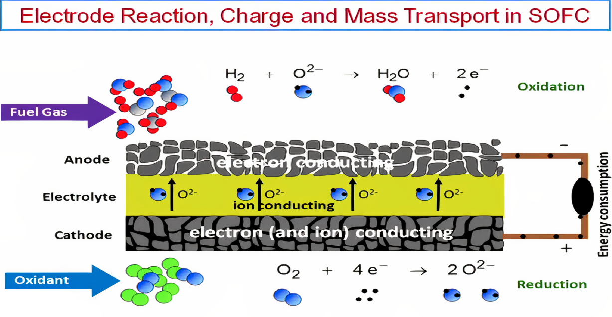
| Cathode | Electrolyte | Anode |
| microstructural porosity; mixed conductivity ( for oxide ion and electrons). | must be a highly dense solute that has only ionic conductivity for oxide ions. | microstructural porosity; electrical conductivity. |
| Anode | O2 + 4 e- + 4 H+ → 2 H2O | E0 = 1.23 V |
| Cathode | H2 → 2 H+ + 2 e- | E0 = 0.00 V |
| Overall | H2 + 1/2 O2 → H2O | Δ Gf = -229 kJ/mol |
| Electrolyte (Dense Solid) | Gadolinium and Samaria doped Ceria |
| Anode (Porous Solid) | Fe mixed Ni - GDC cermet |
| Cathode (Porous Solid) | Co and Fe doped Lanthanum Ferrite La0.6Sr0.4Co0.2Fe0.8O3 |
| Interconnect (Joint in series / Parallel stack) | Ferritic steel (20-24% Cr) |
| Sealant | Boro Aluminium Silicate [3] [7] |
Configuration

There are two major ways of cell design configuration.
- Planar
- Tubular
- Electrolyte-supported
- Anode-supported
- Cathode-supported
Among these, anode-supported configurations suit our needs the best. Cells built with an anode as the support structure have the advantage of having a thin electrolyte membrane. This dramatically reduces the ohmic loss attributed to the electrolyte thickness, which enables a lower operating temperature and higher performance. The lower operating temperature greatly reduces degradation (related to the corrosion of the ancillary reactant delivery equipment and adverse effects on the cell), thereby increasing lifetime. Additionally, this design has a thin cathode layer that provides an opportunity for tailoring the cathode material formulation to enhance performance or provide chemical resistance for various applications. A downside to anode-supported cells is that the nickel cermet support must be porous to allow for gas diffusion; thus, it is harder to seal the periphery. In addition, the diffusion resistance of the anode gases through this thick anode support structure makes it difficult to achieve high single-pass fuel utilization.
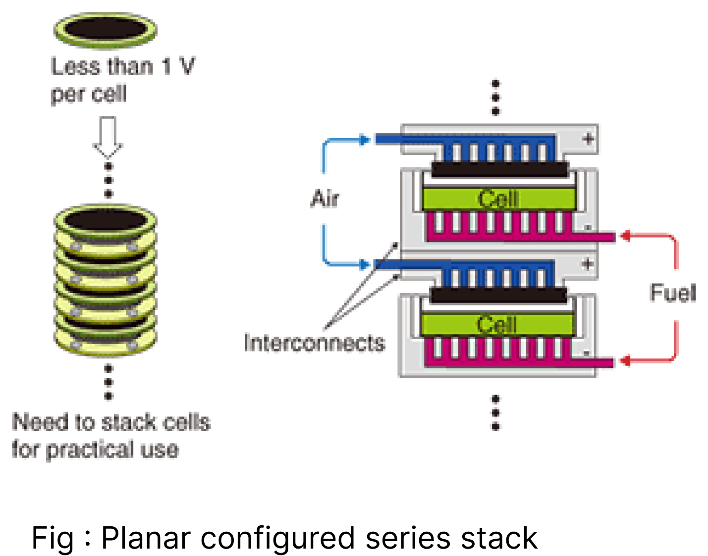
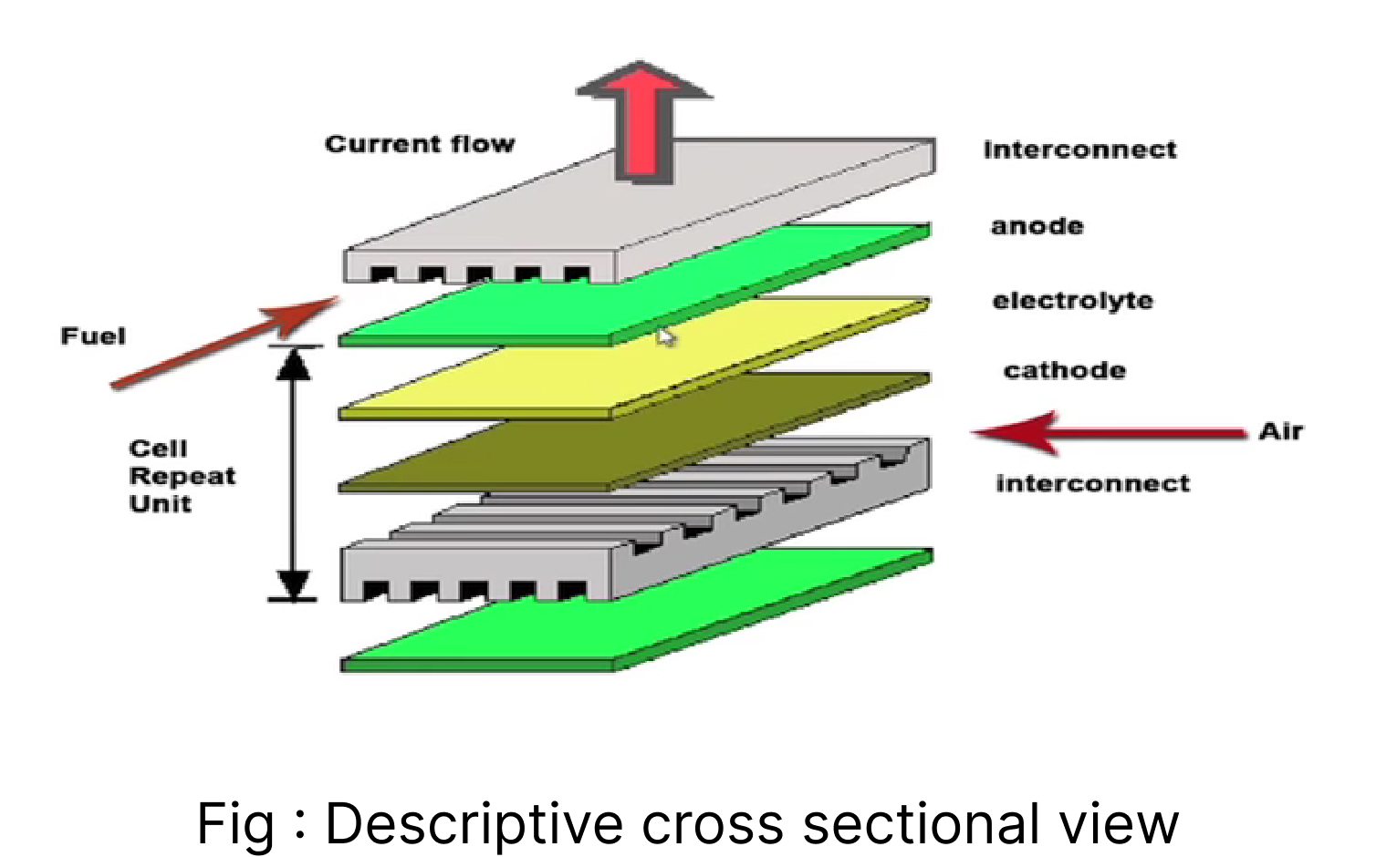
Single-cell can’t provide the required energy, so stack technology connects numerous cells in series and parallel. Therefore, we use interconnects made up of metallic alloy (Ferritic steel) with grooves for fuel and oxidant flow to connect one anode to another cathode. Gaseous flow is designed such that fuel is flown in contact with the anode and air is flown in contact with the cathode. And to prevent their mixing, Boro Aluminium Silicate is used because it can withstand the temperature of Venus.[7] Cathode, anode, and electrolyte are sandwiched on a glass plate. The airflow vent system is managed with the help of grooves of the plate, indicated by the red arrow as the fuel flows in contact with the anode; the blue arrow as an oxidant in contact with the cathode. Sealing glass to prevent the mixing of two gases.
Cathode, anode, and electrolyte sandwiched on a glass plate, air flow vent system is managed with the help of grooves of the plate, indicated red arrow as the fuel flows in contact with anode; blue arrow as an oxidant in contact with the cathode. Sealing glass is used to prevent the mixing of two gases.
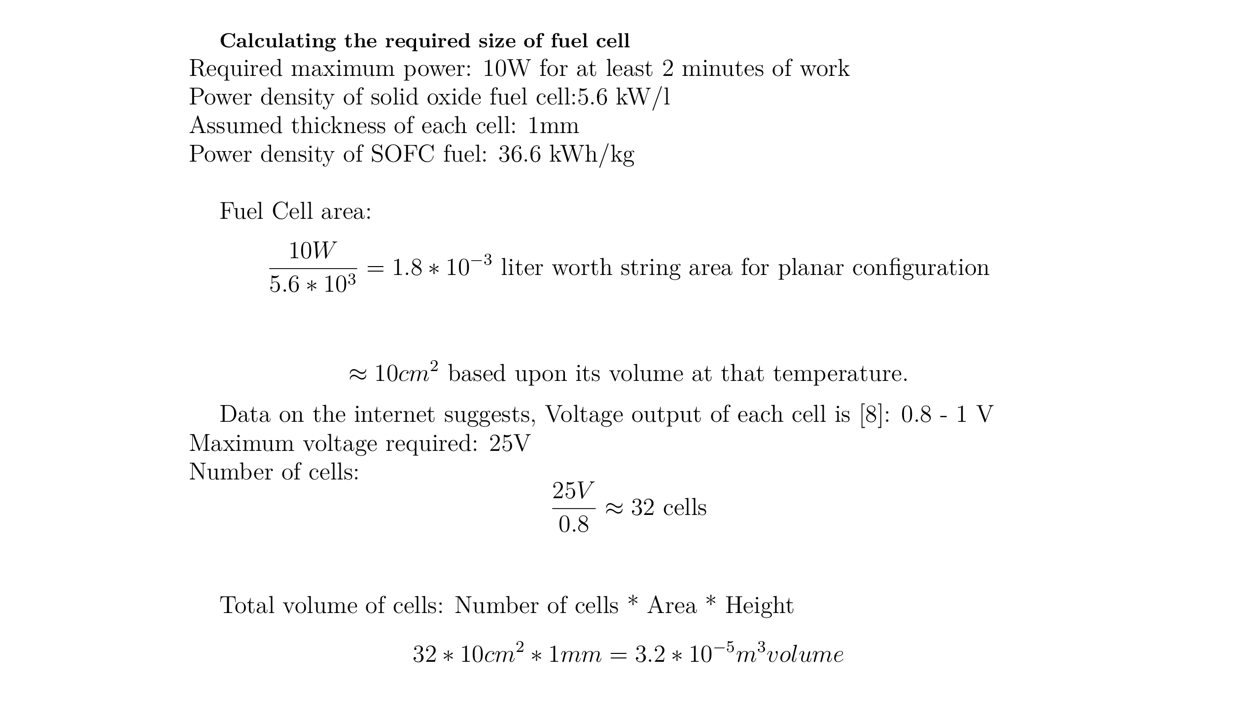
Fuel cell size
Fuel cell mass

Arrangement of energy source

Overall working of the Power System
Fuel cell compartment is placed below the main system vessel. Gaseous containers are in main compartment and gases are passed to electrodes through mechanical motors and valve system which are controlled to provide intermittent supply. Such system can operate in any orientation. Byproducts and unreacted gases are contained in byproduct container and released through two-door system to manage pressure difference. Fuel cell is contained in pressure vessel made up of Nickel alloy containing inert gas inside that prevents active components from corrosion and pressure. But vessel conducts heat to maintain operating temperature inside fuel cell compartment.
References
[1] - https://solarsystem.nasa.gov/planets/venus/overview/ [2] - https://trs.jpl.nasa.gov/bitstream/handle/2014/53729/CL%2320-6470.pdf?sequence=1 [3] - https://link.springer.com/content/pdf/10.1557/mrs.2014.192.pdf [4] - https://www.sciencedirect.com/science/article/pii/S2214157X22001149 [5] - https://www.youtube.com/watch?v=dWWcC42QD9o&ab_channel=nptelhrd [6] - https://www.researchgate.net/figure/Different-planar-SOFC-single-cell-configurations-the-electrolyte-supported-a-cathode_fig1_45834949 [7] - https://www.mdpi.com/1996-1073/14/5/1280 [8] - https://www.sciencedirect.com/topics/engineering/solid-oxide-fuel-cell-systems